Introduction
External adapters play a critical role in the modern electronics ecosystem. They are widely used in laptops, smart home devices, medical equipment, and industrial control systems, serving as the interface between AC mains and the sensitive electronic circuits they power. As such, the reliability and lifetime of these adapters are paramount. A failure in an external adapter can lead to device malfunction, safety hazards, or reduced product life, resulting in costly downtime and increased customer dissatisfaction.
1. Importance of Reliability in External Adapters
1.1 Impact of Reliability on Product Performance
The reliability of an external adapter directly affects the downstream device. A poorly designed adapter can cause:
- Voltage fluctuations leading to device instability
- Overheating reduces the lifespan of both the adapter and the device
- Electrical leakage or short circuits create safety hazards
In critical applications like medical equipment, industrial automation, or aerospace, adapter failures can have severe consequences. High reliability is therefore essential.
1.2 Lifetime and Maintenance Cost
The lifetime of an adapter defines its total cost of ownership. Short-lifespan adapters require frequent replacement, increasing maintenance costs and reducing user satisfaction. By designing for an extended lifetime, manufacturers can achieve:
- Lower warranty costs
- Reduced replacement frequency
- Enhanced brand reputation and customer trust
2. MTBF Calculation
2.1 Concept of MTBF
MTBF (Mean Time Between Failures) represents the expected average operational time before a failure occurs. It is a key metric for reliability engineering, especially in electronic power supplies.
Empirical formula:
MTBF = Total_Operating_Time / Number_of_Failures
A higher MTBF indicates a longer average operational lifespan and better reliability.
2.2 Methods for MTBF Calculation
2.2.1 Component Reliability Modeling
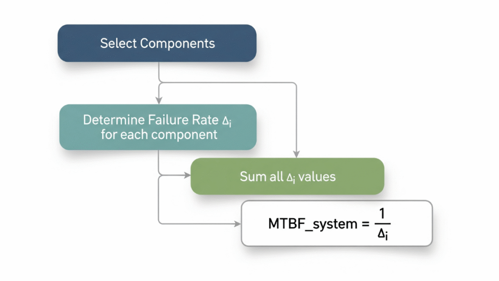
MTBF can be estimated using the failure rate of individual components. The MIL-HDBK-217F and Telcordia SR-332 standards provide failure rate data for capacitors, semiconductors, resistors, and other components. The combined MTBF for an adapter is calculated using:
MTBF_system = 1 / (λ1 + λ2 + λ3 + ... + λn)
Where λi is the failure rate of component i (failures per hour).
Example table: Component failure rates
| Component Type | Failure Rate (λi) per 10^6 hours | Notes |
|---|---|---|
| Electrolytic Capacitor | 0.5 – 1.5 | Depends on temperature, ripple |
| Switching IC | 0.05 – 0.1 | Power dissipation dependent |
| Resistor | 0.01 – 0.05 | Temperature and load dependent |
2.2.2 Empirical Measurement Method
MTBF can also be measured experimentally by running multiple adapter units continuously and recording the time to failure. This method is closer to real-world performance but is time-consuming and costly.
2.3 Setting MTBF Targets
Typical MTBF targets vary based on application:
- Consumer adapters: 50,000 – 100,000 hours
- Industrial adapters: 100,000 – 150,000 hours
- Medical-grade adapters: >150,000 hours
3. Electrolytic Capacitor Lifetime Evaluation
3.1 Role of Electrolytic Capacitors
Electrolytic capacitors are often the limiting factor in adapter lifetime. They are sensitive to temperature, voltage stress, and ripple current. Early capacitor failure can lead to output voltage instability, increased ripple, or even complete adapter failure.
3.2 Capacitor Lifetime Model
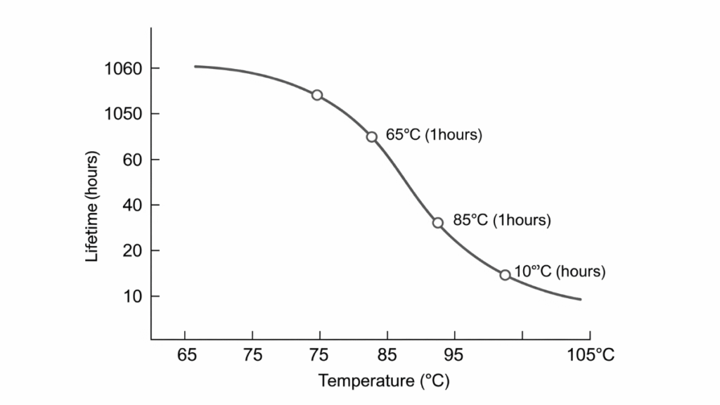
The lifetime of electrolytic capacitors is typically estimated using the Arrhenius model:
Lx = Lr * 2^((T0 - Ta)/10)
Where:
- Lx = lifetime at operating temperature (hours)
- Lr = rated lifetime at T0 (hours)
- T0 = rated temperature (°C)
- Ta = actual operating temperature (°C)
Every 10°C increase in operating temperature roughly halves the expected capacitor lifetime.
3.3 Design Optimization Strategies
- High-temperature capacitors: Use 105°C-rated capacitors for high-reliability designs
- Reduce internal temperature: Improve adapter cooling using heatsinks, thermal vias, and airflow design
- Reduce ripple current: Increase capacitance or use parallel capacitors to distribute current load
Example table: Estimated capacitor lifetime at different temperatures
| Rated Lifetime (105°C) | Operating Temp | Lifetime Estimate (Hours) |
|---|---|---|
| 2000 | 85°C | 8000 |
| 2000 | 75°C | 16000 |
| 2000 | 65°C | 32000 |
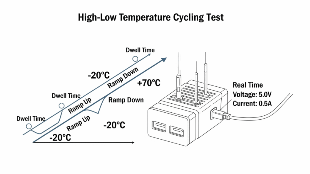
4. High-Low Temperature Cycling Test
4.1 Purpose
High-low temperature cycling tests simulate environmental stress, evaluating adapter tolerance to temperature fluctuations and mechanical stress due to thermal expansion.
4.2 Test Conditions
- Temperature range: -20°C to +70°C (industrial: -40°C to +85°C)
- Cycle count: 10–20 full cycles
- Dwell time: 30–60 minutes at high/low extremes
- Monitoring: Adapter powered on, measuring output voltage, current, and temperature rise
4.3 Test Criteria
- Output voltage deviation: ±5%
- Power loss variation: ≤5%
- No leakage, no smell, no visible capacitor bulging
This test identifies design weaknesses such as mismatched thermal expansion between PCB and components, solder fatigue, and mechanical stress.
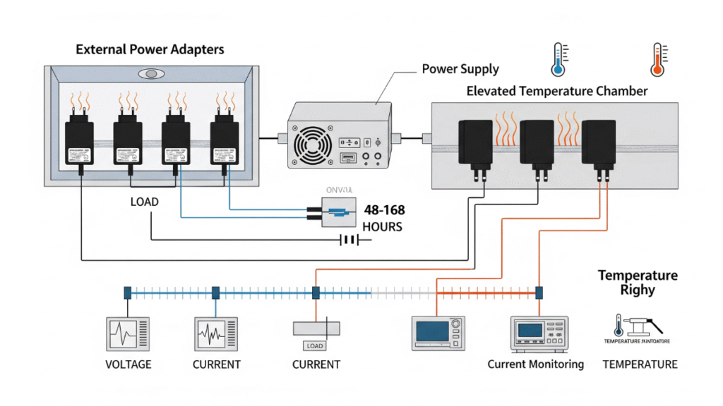
5. Accelerated Aging (Burn-in Test)
5.1 Overview
Burn-in testing accelerates early failures (“infant mortality”) by operating adapters under elevated stress conditions. This improves overall reliability by detecting defective units before shipment.
5.2 Test Setup
- Temperature: Rated + 20–30°C
- Load: Full or 75% load
- Duration: 48–168 hours
- Environment: Dry heat, humid heat, or airflow-controlled chamber
5.3 Failure Modes Detected
| Failure Mode | Cause | Mitigation Strategy |
|---|---|---|
| Capacitor bulging/leak | High ripple current/overheating | Use high-quality capacitors, reduce ripple |
| IC overheat | Insufficient cooling | Improve thermal design |
| Solder joint fatigue | Thermal stress cycling | Optimize PCB layout, use flexible solder |
Burn-in testing ensures reliability under real-world conditions and provides feedback for circuit and component optimization.
6. Comprehensive Lifetime and Reliability Design
6.1 Design-Phase Strategies
- Component selection: Prioritize high-reliability capacitors, inductors, and semiconductors
- Circuit optimization: Minimize ripple current, reduce switching losses
- Thermal design: Efficient heatsinks, thermal vias, airflow management
6.2 Verification-Phase Strategies
- MTBF calculation and validation: Combine theoretical modeling with empirical data
- Burn-in and thermal cycling tests: Identify weak points and validate design robustness
- Iterative design improvement: Refine layout, thermal management, and component selection
6.3 Usage-Phase Strategies
- Environmental adaptation: Ensure operating temperature, voltage, and humidity are within specifications
- Periodic inspection: Visual check, thermal imaging to detect hot spots
- Lifetime prediction: Use MTBF and capacitor lifetime models to predict replacement cycles and support warranty planning
7. Case Studies
7.1 Consumer Laptop Adapter
- Input: 100–240V AC
- Output: 19V 3.42A
- MTBF target: 70,000 hours
- Reliability strategy: 105°C electrolytic capacitors, reinforced PCB thermal vias, burn-in at 60°C 75% load for 72 hours
7.2 Industrial Power Adapter
- Input: 85–264V AC
- Output: 24V 5A
- MTBF target: 150,000 hours
- Reliability strategy: 105°C electrolytic capacitors, high-frequency ceramic capacitors, 20 thermal cycles -40°C/+85°C, burn-in 168 hours full load
7.3 Medical-Grade Adapter
- Input: 100–240V AC
- Output: 12V 2A
- MTBF target: >200,000 hours
- Reliability strategy: Redundant capacitors, low ESR types, enhanced thermal dissipation, comprehensive burn-in, including humidity stress
8. Conclusion
Designing external adapters for lifetime and reliability is a multifaceted engineering challenge. By combining MTBF calculations, capacitor lifetime evaluation, high-low temperature cycling, and burn-in tests, engineers can ensure adapters are robust, safe, and long-lasting. A strategic approach across design, verification, and usage phases guarantees that adapters meet consumer, industrial, and medical reliability standards.
Future trends in power electronics, including higher power density, complex operating environments, and miniaturization, will make lifetime and reliability design even more critical.
References
- MIL-HDBK-217F, “Reliability Prediction of Electronic Equipment,” U.S. Department of Defense, 1991
- Telcordia SR-332, “Reliability Prediction Procedure for Electronic Equipment,” Telcordia Technologies, 2018
- R. Pecht, “Electronic Component Reliability Handbook,” CRC Press, 2012
- K. Kapur, “Power Supply Design and Reliability Analysis,” Wiley, 2015
- J. Davies, “Accelerated Life Testing: Principles and Practices,” Springer, 2017