Introduction
With the widespread adoption of USB Power Delivery (PD) technology in consumer electronics, laptops, and industrial devices, PD power supplies have become mainstream due to their high power density and flexible multi-voltage output. However, electromagnetic compatibility (EMC) remains one of the biggest hurdles in design and mass production certification. Balancing high efficiency, compact size, and low cost while meeting conducted emissions (CE), radiated emissions (RE), and electromagnetic susceptibility (EMS) requirements has become a crucial challenge for engineers.
EMC Design Challenges in PD Power Supplies
Compared with traditional power supplies, PD power supplies face more severe EMC challenges. First, higher power density drives the switching frequency up significantly, typically ranging from 65kHz to 200kHz, with GaN-based solutions reaching the MHz range. This results in much higher dv/dt and di/dt, which are primary sources of EMI.
Second, PD protocols support multiple voltage levels such as 5V, 9V, 15V, and 20V. The output filter must maintain stable performance across these operating conditions. In addition, CC and data lines inside the USB connector are highly sensitive to electromagnetic noise, and improper handling may lead to communication failures. Finally, engineers must strike a balance between improving EMC performance and maintaining efficiency and cost-effectiveness, which often creates conflicting requirements.
Conducted Emissions (CE) Control
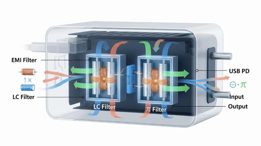
Conducted emissions are generally divided into differential-mode noise and common-mode noise. Differential-mode noise is typically generated by switching currents coupling through bus capacitors to the input lines. LC and π filters are commonly used solutions. LC filters excel in high-frequency suppression and can mitigate inrush current but require larger volume and higher cost. π filters are more compact and cost-effective but increase current stress on the bus capacitors. Thus, practical design often requires trade-offs, with special attention to X-capacitor sizing to ensure leakage current complies with safety standards.
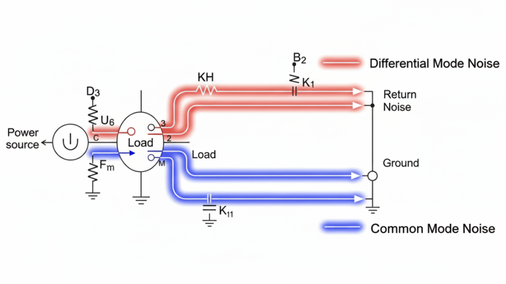
Common-mode noise mainly originates from MOSFET parasitic capacitances and transformer winding parasitics. Noise paths typically flow from switching nodes through parasitic capacitors to the secondary side, then back to LISN ground, or leak via chassis grounding. To suppress common-mode noise, designers often add common-mode chokes at the input, use shielding windings in transformers, and place symmetrical Y capacitors between input and output to return noise currents to the reference ground. PCB layout also plays a crucial role: high dv/dt nodes should be kept away from input lines and sensitive signals to reduce coupling.
Radiated Emissions (RE) Control
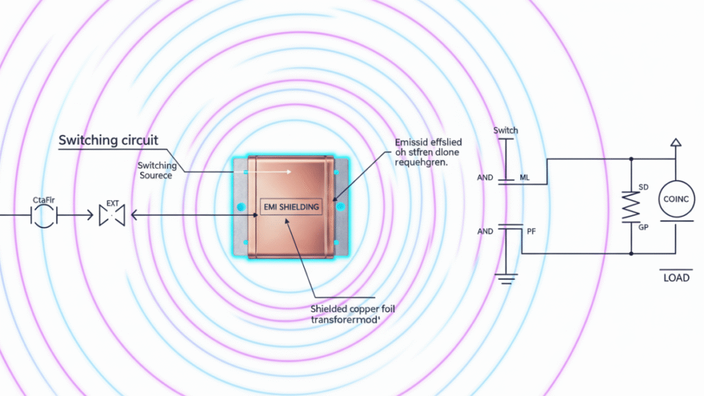
Radiated emissions become critical above 30MHz, primarily caused by high-frequency switching loops acting as antennas. Mitigation measures include adding gate resistors in driver circuits to reduce dv/dt and di/dt, minimizing loop areas among MOSFETs, transformers, and rectifiers on the PCB, and placing Y capacitors near noise sources to divert common-mode currents. RCD snubbers or TVS diodes at the MOSFET drain can help suppress voltage spikes. Shielding is another effective strategy, such as wrapping transformers with grounded copper foil or grounding the USB connector shell to reduce radiation levels.
EMS Immunity Design
Beyond EMI suppression, PD power supplies must also exhibit sufficient immunity. For electrostatic discharge (ESD), TVS diodes are typically placed at USB ports. For electrical fast transients (EFT), RC filters at the input help absorb spikes. Surge protection can be achieved using MOVs in conjunction with common-mode chokes. For voltage dips (DIP), large input capacitors combined with firmware control strategies ensure short-term power stability.
Key Principles in PCB Layout
PCB layout is often the decisive factor in EMC success. High-frequency switching loops must be minimized to reduce parasitic inductance and loop area. Signal ground and power ground should be separated and connected at a single point to avoid ground loops. USB CC and data lines should be routed away from high dv/dt nodes to prevent protocol disturbances. A multi-layer PCB with continuous ground planes is highly recommended to enhance shielding and noise suppression.
Engineering Practice and Debugging Insights
In practice, simulation and prototype validation are powerful tools for identifying EMC issues early. For example, LTspice or PLECS can be used to predict differential current distribution, while HFSS or CST can simulate radiation paths. During debugging, a step-by-step elimination method is recommended: test without Y capacitors first to evaluate differential-mode issues, then gradually identify common-mode paths, and finally fine-tune with shielding and layout improvements.
To ensure production consistency, it is advisable to design with a margin of 3–6 dB, preventing batch failures in compliance testing. In terms of filter selection, π filters can be used for quick validation, later replaced by LC structures for better performance-size trade-offs.
Conclusion
PD power supply EMC design is a systematic engineering task that requires addressing both conducted and radiated emissions, as well as ensuring robustness under various immunity tests. Proper circuit design, filter selection, PCB layout, and debugging strategies are all essential. With the increasing adoption of GaN devices pushing switching frequencies higher, EMC challenges continue to grow. Only by incorporating EMI and EMS considerations into the early design phase, combined with practical debugging experience, can engineers deliver truly reliable and competitive PD power supply products.